When a machine component breaks and its original drawings are unavailable, replacing it can become a difficult engineering task. The manufacturer may need to locate an obsolete part, measure an existing component or develop a replacement that fits an assembly with tight dimensional requirements.
For Australian manufacturers, combining 3D scanning, computer-aided design (CAD) and 3D printing offers a practical way to approach these challenges. The process captures the geometry of a physical component, converts the data into a usable digital model and helps engineers assess suitable manufacturing methods.
Why Traditional Part Replacement Can Be Difficult
Conventional replacement methods often depend on engineering drawings, supplier availability or manual measurements. These options can become time-consuming when dealing with complex surfaces, irregular shapes, worn components or discontinued products.
Manual measurements may be sufficient for simple brackets and spacers. However, parts with curved profiles, intricate features or multiple mating surfaces can require more detailed dimensional information.
This is where digital measurement and reverse engineering can assist. Rather than starting a design from scratch, engineers can use an existing component as a reference for developing a new CAD model.
How 3D Scanning Supports Reverse Engineering
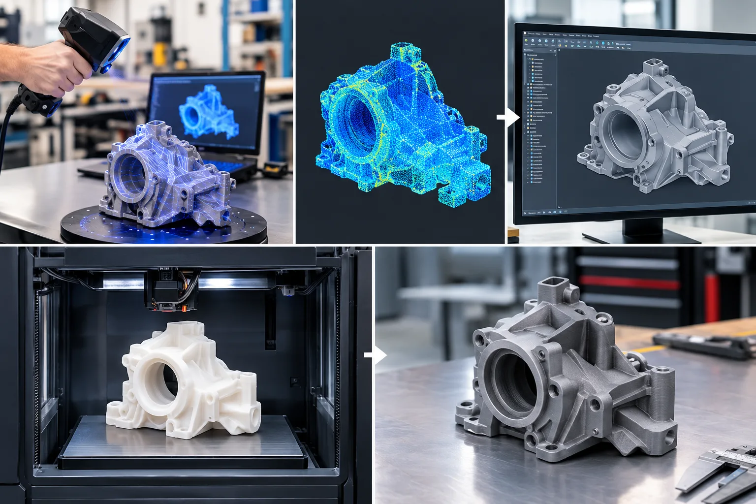
3D scanning captures the surface geometry of a physical object and generates digital data that can be processed for engineering applications. Depending on the scanning method and component, the output may include a point cloud or polygon mesh.
The data can help engineers understand features that are difficult to capture using basic measuring tools, including complex contours, surface transitions and irregular profiles.
A typical reverse-engineering workflow involves:
- Component assessment: Identify the part's function, material, condition and critical interfaces.
- 3D data capture: Scan the component using a suitable measurement system.
- Data processing: Remove unwanted scan data and align multiple scans where necessary.
- CAD reconstruction: Rebuild the geometry using appropriate modelling techniques.
- Dimensional verification: Compare critical features against available measurements, drawings or mating components.
The scan is a reference, not automatically a production-ready CAD model. Engineers may need to reconstruct design intent, restore worn surfaces, define tolerances and confirm dimensions before manufacturing.
Businesses exploring this workflow can review 3D scanning services in Melbourne, 3D scanning services in Brisbane and 3D scanning services in Perth.
Converting Scan Data into a Manufacturing-Ready CAD Model
Once the geometry has been captured, the next stage is to create a usable digital model. This requires more than tracing the scanned surface.
Engineers must determine which features should be preserved, which surfaces need reconstruction and which dimensions control the component's fit or function. Holes, mounting points, wall thicknesses and mating faces may require particular attention.
The final model should reflect the component's engineering requirements rather than simply reproduce every surface irregularity in the scan.
File formats also matter. Mesh formats such as STL and OBJ represent surfaces using polygons, while STEP and IGES can transfer CAD geometry between compatible engineering systems. The appropriate format depends on whether the next stage involves visualisation, further modelling, machining or additive manufacturing.
Before production, engineers should check dimensional accuracy, clearances, material requirements and any relevant operating loads.
When 3D Printing Is Suitable for Replacement Parts
After the CAD model has been checked, 3D printing may provide a suitable manufacturing route for prototypes, custom components and selected low-volume replacement parts.
The best process depends on the part's geometry, intended use, material properties, production quantity and required surface finish.
- Fused deposition modelling (FDM): Often considered for functional prototypes, fixtures, housings and selected polymer components.
- Selective laser sintering (SLS): Can suit complex polymer parts that benefit from geometric freedom and reduced reliance on dedicated support structures.
- Multi Jet Fusion (MJF): Often used for functional polymer components and small production runs, subject to design and material requirements.
- Stereolithography (SLA): Useful for detailed prototypes and parts requiring fine surface detail, depending on the resin's mechanical and environmental properties.
Metal additive manufacturing may also be appropriate for selected engineering applications, although cost, material qualification and post-processing requirements need careful assessment.
3D printing is not automatically the best option for every replacement component. Parts exposed to high temperatures, repeated fatigue, impact, pressure or safety-critical loads may require conventional machining, certified materials or a more extensive engineering assessment.
Manufacturers can compare these considerations with the capabilities described on the 3D printing services in Australia page.
What About 3D Printing in Melbourne?
For businesses in Melbourne, the choice between scanning, CAD reconstruction and manufacturing depends on the component and its application.
A simple plastic cover may only require basic measurements and a revised CAD model. A complex automotive trim component could require scanning, surface reconstruction and several prototype iterations before its mounting points and clearances are acceptable.
The same principle applies to industrial equipment, custom enclosures, assembly fixtures and discontinued non-safety-critical components.
Access to a local service provider can help businesses discuss design files, material options, dimensional requirements and production quantities before committing to a manufacturing method. For relevant project requirements, see 3D printing in Melbourne.
How to Prepare a Component for Scanning and Reproduction
A few practical steps can improve the quality of the engineering assessment:
- Clean the component where appropriate, without removing important surface features.
- Identify damaged or worn areas so they are not mistakenly treated as the original design.
- Provide photographs showing the component from multiple angles.
- Supply existing drawings, CAD files or measurements if available.
- Identify mating parts, mounting interfaces and critical dimensions.
- Explain the operating environment, including temperature, chemicals, loads and exposure conditions.
- State the intended production quantity and any material or compliance requirements.
These details help engineers distinguish between a visual replica and a functional replacement designed for a specific application.
Bringing Digital Engineering and Manufacturing Together
The combination of 3D scanning, reverse engineering, CAD modelling and additive manufacturing gives Australian businesses another option for addressing difficult component-replacement and prototyping problems.
The key is to treat each stage as part of a connected engineering process. Accurate data capture supports CAD reconstruction, sound modelling decisions support manufacturability, and appropriate material selection helps determine whether a printed part is suitable for its intended purpose.
For manufacturers, maintenance teams and product developers, this approach can support more informed decisions about how to reproduce, modify and test physical components before moving to production.