

How Plunger Lift Helps Boost Gas Well Production
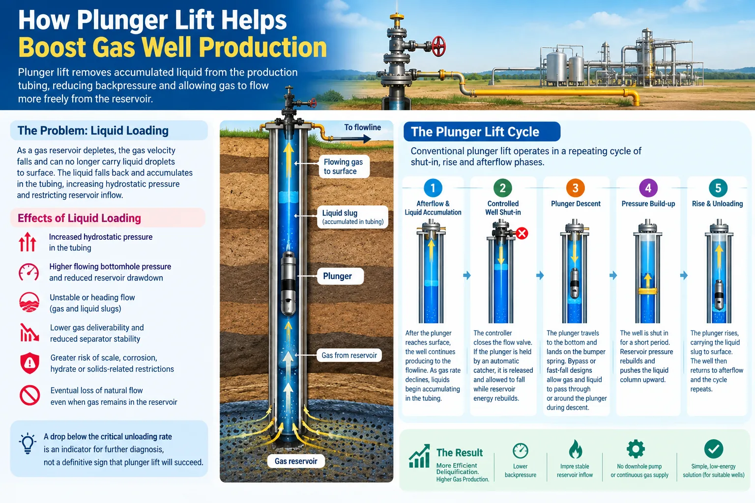
As a gas reservoir depletes, declining pressure and gas velocity reduce the well's ability to transport produced water and hydrocarbon condensate to surface. When the upward gas velocity falls below the level required to entrain these liquids, droplets begin to fall back and accumulate in the tubing or lower wellbore. The resulting hydrostatic head increases flowing bottomhole pressure, restricts reservoir inflow and can eventually prevent the well from flowing.
Plunger lift is an intermittent or continuous-cycling artificial-lift method designed to remove this accumulated liquid. A free-travelling plunger moves through the production tubing and forms a dynamic mechanical interface between the driving gas below and the liquid slug above. By reducing gas bypass and liquid fallback during unloading, the system can deliquify the well more efficiently than unassisted intermittent flow.
For technically suitable wells, plunger lift offers a comparatively simple, low-energy method of maintaining production without a downhole pump or a continuous external gas-injection supply. Its performance, however, depends on correct candidate selection, compatible tubing geometry, sufficient pressure differential, suitable plunger design and continuous cycle optimisation.
Quick Answer: How Does Plunger Lift Increase Gas Production?
Plunger lift increases gas-well production by periodically removing liquid that has accumulated in the production tubing. Clearing this liquid reduces hydrostatic backpressure on the reservoir, lowers flowing bottomhole pressure and allows gas to enter the wellbore more readily. The plunger improves unloading efficiency by separating the lifting gas from the liquid slug and limiting fluid fallback during travel to surface.
Why Liquid Loading Reduces Gas-Well Performance
At sufficiently high velocity, produced gas carries entrained liquid droplets upward through the tubing. As reservoir pressure and gas rate decline, the gas may no longer provide enough drag force to overcome gravity acting on the droplets. Liquid then falls back, coalesces and accumulates in the well.
This condition, known as liquid loading, produces several adverse effects:
- Increased hydrostatic pressure in the production tubing.
- Higher flowing bottomhole pressure and reduced reservoir drawdown.
- Unstable or heading flow, with alternating gas and liquid slugs.
- Lower gas deliverability and reduced separator stability.
- Greater risk of scale, corrosion, hydrate or solids-related restrictions.
- Eventual loss of natural flow even when recoverable gas remains in the reservoir.
The critical unloading condition is well-specific. It depends on gas and liquid properties, tubing diameter, pressure, temperature, well inclination and flow regime. A production decline below a calculated critical rate is therefore an indicator for further diagnosis rather than, by itself, proof that a particular lift method will be successful.
What Is Plunger Lift?
Plunger lift is an artificial lift system that uses a travelling downhole plunger and the well's available pressure energy to transport liquids through the production tubing. Unlike rod lift or electric submersible pumping, a conventional plunger-lift system does not use a mechanically driven downhole pump. Unlike conventional gas lift, it does not normally require continuous injection of compressed gas through downhole valves.
The plunger is sized with controlled clearance relative to the tubing ID. Depending on the design, it may use a bar-stock body, expanding pads, a brush sealing section, a bypass valve or another sealing geometry. During upward travel, the plunger reduces the amount of gas that channels through the liquid slug and limits liquid fallback around the lifting interface.
Conventional plunger lift operates in defined shut-in, rise and afterflow phases. Fast-fall, bypass and continuous-flow systems can reduce or eliminate part of the shut-in period where the well conditions and equipment design permit.
How a Conventional Plunger-Lift Cycle Works
A typical cycle comprises the following stages:
- Afterflow and liquid accumulation: After the plunger reaches surface, the well continues producing to the flowline. As gas rate declines during this period, liquids begin accumulating in the tubing.
- Controlled well shut-in: The controller closes the automated flow valve. If the plunger is being held by an automatic catcher, it is released from the surface lubricator and allowed to fall through the tubing while reservoir energy rebuilds.
- Plunger descent: The plunger travels to the bottom of the tubing and lands on the downhole bumper spring. Bypass or fast-fall designs allow gas and liquid to pass through or around the plunger during descent.
- Pressure build-up: With the well shut in, casing and tubing pressure increase. Liquids collect above the plunger while gas pressure develops below it.
- Well opening and plunger rise: When the programmed time or pressure criteria are satisfied, the controller opens the motor valve. The resulting differential pressure drives the plunger upward with the accumulated liquid slug above it.
- Surface arrival: The plunger enters the lubricator, and an arrival sensor confirms its return. The produced liquid is routed through the surface production system, and the catcher may retain the plunger until the next cycle.
- Gas-production afterflow: With much of the liquid column removed, the well flows at reduced backpressure. The controller maintains afterflow until the selected pressure, rate or time limit indicates that another unloading cycle is required.
Cycle logic varies with the plunger type, controller algorithm, completion geometry and well behaviour. Pressure- and rate-responsive control is generally more adaptable than fixed timing alone because reservoir inflow and flowline conditions change throughout the well's producing life.
Main Components of a Plunger-Lift System
ComponentLocationTechnical functionPlungerInside the production tubingCreates a dynamic interface between lifting gas and produced liquid while travelling between the bottomhole assembly and surfaceBumper spring and tubing stopDownhole, near the lower end of the tubingStops the plunger at the required depth and absorbs impact during descentLubricatorSurface, above the wellheadReceives the arriving plunger and provides controlled access for inspection, installation or removalCatcherSurface lubricator assemblyHolds or releases the plunger as required by the operating cycle and maintenance procedureArrival sensorSurface lubricator assemblyDetects plunger arrival and transmits the event to the controllerController and pressure sensorsSurfaceManage shut-in, opening and afterflow using time, casing pressure, tubing pressure, line pressure, flow rate or calculated conditionsAutomated motor valveSurface flowlineOpens or closes the well in response to controller commandsSeparator and production facilitiesSurfaceReceive the gas and liquid slug while maintaining acceptable flowline backpressure and handling capacityThe lubricator assembly is normally designed to manage the impact of the plunger at surface. The bumper spring, however, is a bottomhole component that cushions the plunger when it reaches the lower tubing stop.
How Plunger Lift Improves Production
Reduces Hydrostatic Backpressure
Removing accumulated water or condensate decreases the liquid head acting on the producing formation. The corresponding reduction in flowing bottomhole pressure increases available drawdown and can restore gas inflow.
Improves Liquid-Unloading Efficiency
Without a plunger, lifting gas can channel through the liquid column while part of the liquid falls back. The plunger provides a moving interface that reduces gas slippage and fallback, enabling more of the accumulated liquid to reach surface during each unloading event.
Stabilises Intermittent Production
Automated cycle control replaces irregular self-unloading or manual intervention with repeatable operating phases. More stable pressure behaviour can improve production forecasting and reduce severe liquid-slug disturbances at the surface facilities.
Extends the Economic Producing Life
A well that cannot flow continuously may still contain sufficient reservoir energy for controlled plunger operation. Effective deliquification can defer abandonment or transition to a more energy-intensive lift method.
Reduces Downhole Equipment Complexity
Conventional plunger lift has no downhole pump, rod string, electric motor or power cable. This can reduce installation and operating complexity where the well meets the required lift conditions.
Which Wells Are Suitable for Plunger Lift?
Plunger lift is commonly evaluated for gas wells and high-gas-to-liquid-ratio wells that are approaching or operating below their natural liquid-unloading rate. A screening assessment should consider:
- Current and forecast gas, water and condensate production rates.
- Static and flowing casing, tubing and wellhead pressures.
- Sales-line or separator pressure and its variability.
- Available opening differential pressure after shut-in.
- Tubing OD, ID, depth, connections, restrictions and internal condition.
- Well inclination, dogleg severity and horizontal geometry.
- Gas-to-liquid ratio and expected liquid-slug volume.
- Reservoir inflow and pressure-build-up response.
- Sand, scale, paraffin, salt or corrosion exposure.
- Plunger fall time, rise time and acceptable arrival velocity.
- Surface-facility capacity to receive cyclic liquid slugs.
The required pressure differential must be sufficient to overcome the weight of the plunger and liquid slug, frictional losses, tubing pressure and flowline backpressure. Candidate selection should therefore use current well data and an integrated inflow, outflow and cycle analysis rather than a single pressure or production-rate threshold.
Common Plunger Types
Plunger geometry is selected to match the well's pressure, liquid rate, tubing condition, deviation and solids environment.
- Bar-stock plungers: Robust conventional designs used where tubing condition and available differential pressure support an appropriate operating clearance.
- Pad plungers: Use spring-loaded or expanding pads to maintain contact and sealing performance in worn or variable-ID tubing.
- Brush plungers: Use flexible brush elements to conform to tubing irregularities and can be useful where wall wear or deposits affect conventional sealing.
- Bypass or fast-fall plungers: Incorporate a valve or internal flow path that increases descent rate and can shorten the shut-in phase.
- Continuous-flow or friction-bypass plungers: Designed to fall against partial or continuing flow, enabling frequent unloading with limited or no conventional shut-in period in suitable wells.
- Solids-tolerant plungers: Use geometries and materials selected to manage abrasion, debris and the risk of solids interference.
No plunger type is universally optimal. A design that falls efficiently in one well may travel too slowly, leak excessively or arrive at an unacceptable velocity in another.
Selection criterionPlunger liftGas liftPrimary lifting mechanismCyclic travel of a plunger driven by available well pressureInjection gas reduces the density of the produced-fluid columnExternal injection gasNot normally required for conventional operationRequired from a compressor or field gas-injection systemTypical flow modeCyclic; continuous-flow variants are availableContinuous or intermittent injectionDownhole equipmentPlunger, bumper spring and tubing stopGas lift valves installed in conventional or side-pocket mandrelsSurface equipmentLubricator, catcher, arrival sensor, controller and motor valveCompressor or injection-gas supply, control and metering equipmentSuitable operating envelopeLiquid-loaded gas wells with sufficient energy and manageable liquid-slug volumesWells requiring additional lifting energy or handling broader liquid-rate conditionsMain optimisation variablesShut-in time, opening pressure, afterflow, fall time, arrival time and velocityInjection depth, injection pressure, gas rate, valve spacing and operating-valve performanceTypical operational considerationTubing access, plunger travel and cyclic slug handlingCompression capacity, injection-gas availability and valve-system integrity
Plunger Lift vs Gas Lift
Plunger lift and gas lift both reduce the effect of accumulated liquids, but they use different energy-transfer mechanisms.
In a conventional gas-lift installation, compressed gas is injected from the casing annulus into the production tubing through gas lift valves and gas lift mandrels. The injected gas reduces the density and hydrostatic gradient of the produced-fluid column. Plunger lift instead uses a travelling mechanical interface and the well's available pressure differential to lift a discrete liquid slug.
When Plunger Lift Is Generally Preferred
Plunger lift is often evaluated first when the well has enough pressure build-up to produce repeatable plunger arrivals, liquid rates are within the selected system's capacity, tubing geometry permits free travel and minimising external energy consumption is a priority.
When Gas Lift May Be More Appropriate
Gas lift may be favoured where the well cannot generate adequate differential pressure for plunger cycling, liquid production exceeds the practical plunger-lift envelope, continuous production is operationally preferable or an established compression and gas-distribution network is already available.
Hybrid arrangements, including plunger-assisted gas lift, may extend the operating envelope. Final selection should be based on production modelling, life-cycle economics, surface constraints and the expected decline profile.
How Gas Lift Valves and Mandrels Function
Gas lift mandrels are tubing-string components that provide a housing and controlled communication path for gas lift valves. In a side-pocket mandrel, the valve is installed off the primary tubing bore and may be retrieved by an appropriate intervention method without pulling the tubing.
During conventional gas-lift operation, high-pressure injection gas travels down the casing-tubing annulus, enters the selected valve and flows into the production tubing. Unloading valves positioned at shallower depths may open sequentially during well start-up. As the fluid level and pressure conditions change, injection transfers to progressively deeper valves until the intended operating valve is reached.
This system can supply lifting energy where natural well pressure is insufficient for reliable plunger operation, but it requires appropriately rated mandrels, valves, annular integrity, injection-gas control and surface compression capacity.
The Role of Sand Screens in Plunger-Lift Wells
Sand screens are formation-sand-control devices, not standard components of a plunger-lift system. They are installed at or across the producing interval when the completion requires mechanical retention of formation sand or proppant while permitting hydrocarbons to enter the wellbore.
Where significant sand production is expected, a properly engineered screen or gravel-pack completion may reduce the solids entering the tubing and thereby limit:
- Abrasive wear of the plunger and tubing wall.
- Damage to valves, chokes and surface equipment.
- Solids accumulation around the bottomhole bumper spring.
- Plunger sticking caused by deposits or packed debris.
- Erosion and instability within the production system.
However, a sand screen should not be installed solely because a plunger-lift system is present. Screen selection requires formation-particle-size data, completion geometry, inflow distribution, drawdown, erosion resistance, plugging risk and productivity analysis. Even a correctly designed screen may not exclude all fines, scale, salt or corrosion products.
In solids-producing wells, the overall strategy may also require a solids-tolerant plunger, controlled drawdown, chemical treatment, periodic cleanout, erosion monitoring or surface solids handling. Sand control and artificial lift should therefore be engineered as coordinated but distinct completion functions.
Plunger-Lift Design and Installation Best Practices
1. Establish a Reliable Well-Performance Baseline
Collect stabilised gas and liquid rates, pressure data, fluid properties, flowline conditions and production history. Confirm that liquid loading—rather than reservoir damage, a restriction, a closed valve or another mechanical problem—is the primary cause of decline.
2. Confirm the Complete Tubing Drift
Review tubing ID, connection profiles, nipples, safety valves, scale, deformation and other restrictions across the full plunger-travel path. The selected plunger and bottomhole assembly must pass and operate within the available drift.
3. Model the Lift Cycle
Estimate liquid-slug volume, pressure build-up, plunger fall time, rise time, frictional loss and surface backpressure. Confirm that the well can deliver acceptable arrival performance without excessive impact velocity.
4. Match the Plunger to the Well
Select the sealing method, bypass area, material and OD for the actual tubing condition, solids environment and operating phase. Consider how the chosen design will respond as reservoir pressure and liquid rate continue to decline.
5. Select and Position the Bottomhole Assembly
The tubing stop and bumper spring must be compatible with the tubing, plunger and deployment method. Positioning should support efficient liquid collection while avoiding known restrictions or damaged sections.
6. Verify Surface Equipment Ratings
The lubricator, catcher, sensor, valve and connecting equipment must be pressure-rated and compatible with the wellhead configuration and produced fluids. Surface facilities must safely receive the cyclic gas and liquid rates.
7. Commission With Controlled Cycle Parameters
Initial shut-in and opening conditions should provide adequate lifting energy without causing excessive surface-arrival velocity. Confirm reliable arrival detection and inspect early production response before increasing cycle frequency.
8. Optimise From Measured Performance
Use tubing, casing and line pressure; plunger arrival; fall and rise time; afterflow; gas rate; and liquid recovery to refine the controller logic. Reassess the programme as well pressure, liquid rate or sales-line conditions change.
Common Plunger-Lift Problems and Corrective Actions
Operating symptomPossible causesEngineering responsePlunger does not arriveInsufficient differential pressure, excessive liquid slug, tubing obstruction, poor plunger seal or high flowline pressureVerify pressures and valve operation, extend build-up if justified, reduce liquid per cycle, inspect the plunger and confirm tubing accessPlunger arrives lateExcessive fallback, worn plunger, high friction, deposits, increasing liquid rate or inaccurate cycle settingsReview arrival history, inspect wear, assess scale or paraffin and retune opening criteriaArrival velocity is excessiveExcessive shut-in pressure, overly long build-up or insufficient liquid loadReduce unnecessary build-up, adjust controller limits and confirm the lubricator and impact-management systemPlunger falls too slowlyHigh counterflow, restrictive plunger geometry, tubing deviation, viscous liquid or depositsEvaluate a fast-fall or bypass design, adjust catcher release timing and inspect the travel pathPlunger sticks repeatedlySand, scale, paraffin, tubing damage, ID restriction or unsuitable plunger typeIdentify the restriction, clean or remediate the tubing, review solids control and select a more appropriate plunger geometryShort or unstable afterflowRapid liquid reloading, high sales-line pressure, poor reservoir inflow or incorrect control logicReview surface backpressure, inflow performance and pressure- or rate-based cycling parametersHigh plunger or tubing wearExcessive arrival speed, high solids loading, poor material selection or over-cyclingControl velocity and cycle frequency, inspect equipment and reassess materials and solids managementRepeatedly extending shut-in time is not a universal solution. Although it may increase opening pressure, it also reduces producing time and can increase arrival velocity. Optimisation should maximise net gas production over the complete cycle rather than simply ensuring that the plunger reaches surface.
When Should an Operator Transition to Another Lift Method?
Plunger lift may reach its practical limit when available pressure no longer supports repeatable unloading, liquid rate exceeds the system capacity, plunger travel becomes unreliable or required shut-in time causes unacceptable production loss. At that stage, the operator should reassess the well using updated inflow and outflow data.
Possible next steps include gas lift, velocity-string installation, capillary chemical treatment, rod lift, progressive-cavity pumping, hydraulic pumping or another deliquification method. The preferred option depends on depth, deviation, fluid rate, gas fraction, solids, power availability, intervention cost and remaining reserves.
Frequently Asked Questions
What is the primary purpose of plunger lift in a gas well?
Its primary purpose is to remove accumulated water or condensate from the production tubing so that hydrostatic backpressure is reduced and gas can continue flowing from the reservoir.
Does plunger lift require an external power source?
The lifting energy normally comes from the well's own pressure. Surface controllers, sensors and automated valves still require a pneumatic, solar-electric or other suitable control-power source. Hybrid systems may also use external compression or gas injection.
Can plunger lift operate in deviated or horizontal wells?
Yes, specialised plungers and control strategies can operate in deviated and horizontal well geometries. Deviation, dogleg severity, fluid distribution and the build section can affect descent, arrival reliability and the required gas-to-liquid ratio, so a well-specific analysis is essential.
What is the difference between plunger lift and gas lift?
Plunger lift uses a travelling mechanical interface driven primarily by available well pressure. Gas lift injects compressed gas into the production tubing through valves installed in gas lift mandrels, reducing the density of the produced-fluid column.
How frequently should a plunger cycle?
There is no universal cycle frequency. It should be determined from liquid accumulation, pressure build-up, fall and rise time, arrival velocity, surface backpressure and afterflow performance. Dynamic pressure- or rate-based control can adapt the cycle as well conditions change.
Are sand screens required for plunger lift?
No. Sand screens are used when the formation and completion require sand control. They may help protect the plunger and downstream equipment by limiting solids production, but their use must be justified through a separate sand-control evaluation.
What causes a plunger to stop reaching surface?
Common causes include insufficient pressure differential, excessive liquid load, high sales-line pressure, plunger wear, tubing restrictions, scale, paraffin, sand accumulation or unsuitable cycle settings.
Key Takeaways
- Plunger lift removes accumulated liquids from gas wells by using a travelling plunger and the well's available pressure energy.
- Effective unloading reduces hydrostatic backpressure, lowers flowing bottomhole pressure and can restore gas deliverability.
- A conventional cycle includes shut-in, plunger descent, pressure build-up, upward travel, surface arrival and afterflow.
- The bumper spring is installed downhole; the lubricator, catcher, arrival sensor, controller and motor valve are located at surface.
- Gas lift uses externally supplied injection gas through valves and mandrels, whereas conventional plunger lift normally relies on well pressure.
- Sand screens are application-dependent sand-control equipment, not mandatory plunger-lift components.
- Long-term performance depends on candidate screening, tubing compatibility, cycle modelling, arrival control and continuous optimisation.
Conclusion
Plunger lift can recover gas production that would otherwise be restricted by liquid loading. Its effectiveness comes from combining the well's available pressure energy with a mechanical lifting interface that reduces gas bypass and liquid fallback. When the system is correctly selected and tuned, accumulated water and condensate can be removed with comparatively low downhole complexity and limited external energy demand.
Successful application requires more than installing a plunger and operating on a fixed timer. The complete system—including the tubing, bottomhole stop, bumper spring, plunger, lubricator, sensors, controller, surface valve and production facilities—must be matched to the well's pressure behaviour and decline profile. Continuous review of arrival data, liquid recovery and afterflow performance is essential to maintaining production and identifying when a different artificial-lift method becomes more economical.
For application-specific plunger-lift selection, gas-lift equipment and customised artificial-lift solutions, contact SAZ Oil at [email protected].