

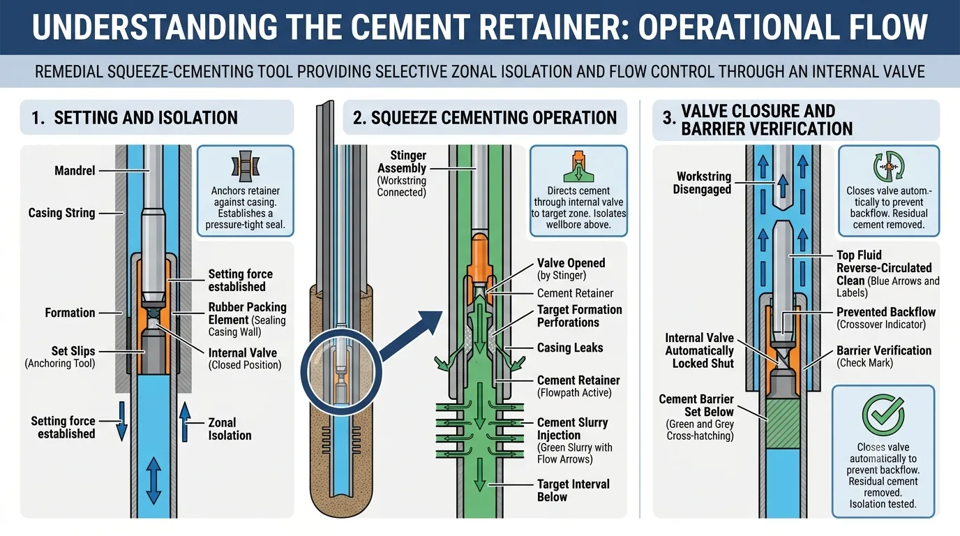
Cement retainers are packer-type downhole isolation tools used primarily to place cement accurately during remedial squeeze-cementing operations. Once set inside casing or liner, a cement retainer anchors against the tubular wall, establishes a pressure-tight seal and provides controlled access to the interval below through an internal valve.
This combination of anchoring, sealing and selective flow control enables engineers to inject cement into perforations, casing leaks or poorly isolated zones without allowing the slurry to migrate back into the wellbore above the tool. Cement retainers are therefore widely applied in zonal isolation, water or gas shutoff, casing repair, recompletion and plug-and-abandonment programmes.
Failed cement placement can result in loss of zonal isolation, additional rig time and costly re-intervention. Correct retainer selection, accurate depth control and a properly engineered squeeze programme are consequently critical to achieving a verifiable barrier on the first attempt.
Quick Answer: What Is the Main Purpose of a Cement Retainer?
The main purpose of a cement retainer is to isolate the wellbore above a target interval while allowing cement to be pumped through the tool and squeezed into the formation, perforations or annular flow path below it. After cement placement, disengaging the workstring closes the retainer valve and prevents backflow into the casing above.
What Is a Cement Retainer?
A cement retainer is a casing- or liner-set isolation device designed specifically for remedial cementing. Although its anchoring and sealing functions resemble those of other downhole packers, its operating objective is different from that of a production packer. A cement retainer incorporates a controllable internal flow path that enables fluids and cement slurry to be pumped below the set depth during a squeeze operation.
In a typical design, the valve is opened when a compatible stinger or seal-bore assembly is engaged. The valve closes when the workstring is disengaged, retaining pressure below the tool and preventing unset cement from flowing back into the wellbore. Depending on the application, the retainer may be drillable, millable or retrievable; the selected design must be consistent with the planned post-cementing operation.
Principal Components
A cement retainer generally includes:
- Mandrel: Carries axial loads and provides the central flow path through the tool.
- Slip and cone system: Anchors the retainer against the casing and resists differential pressure from either direction, subject to the tool design.
- Packing element: Expands radially to form a hydraulic seal against the casing or liner ID.
- Internal valve: Controls communication through the retainer during cement placement and closes when the stinger is disengaged.
- Stinger or seal-bore interface: Connects the workstring to the retainer and provides a sealed pumping path.
- Setting mechanism: Activates the slips and packing element by wireline, mechanical or hydraulic means, depending on the retainer configuration.
How Does a Cement Retainer Work?
The cement retainer creates a sealed anchor above the treatment interval and directs the cement slurry through its internal valve to the required depth. A typical field sequence is as follows:
- Confirm the wellbore condition and target depth. The casing programme, internal diameter, weight, grade, restrictions and pressure limitations are reviewed. The setting depth is correlated using the approved wireline or workstring depth-control method.
- Prepare the casing. Scale, debris or residual cement is removed where necessary. A gauge ring, drift or casing-scraper run may be used to confirm access and provide a suitable setting surface.
- Run and set the retainer. The tool is conveyed to depth and set using the specified wireline, mechanical or hydraulic setting system. The slips engage the casing, and the packing element is compressed to establish isolation.
- Verify the set. The anchoring and sealing integrity are checked in accordance with the operating procedure and the tool's pressure limitations.
- Run and engage the stinger. A compatible stinger assembly is deployed on the workstring and inserted into the retainer. Engagement opens the internal valve and establishes a sealed flow path to the interval below.
- Establish injectivity and pump the cement programme. Preflushes, spacers and cement slurry are pumped at the engineered rates and pressures. Surface pressure, volume and returns are monitored continuously to confirm placement and avoid exceeding formation-fracture, casing or tool limits.
- Apply the squeeze pressure. Cement is displaced into the intended leak path, perforations or annular channel using the selected squeeze technique.
- Disengage and close the valve. The workstring is picked up to release the stinger. The internal valve closes, isolating the cemented interval and preventing backflow.
- Reverse-circulate excess cement. Residual slurry above the retainer is circulated out before it can set in the workstring or casing.
- Wait on cement and verify the barrier. After the specified curing period, the isolation is tested or otherwise verified in accordance with the well programme and applicable regulatory requirements.
The exact sequence varies with the retainer design, setting method, squeeze technique and well conditions. The manufacturer's operating procedure and the approved cementing programme should always govern field execution.
Common Applications of Cement Retainers
1. Remedial Squeeze Cementing
Cement-bond evaluation, pressure testing or production behaviour may indicate inadequate primary cement, microannular flow or channeling behind casing. A cement retainer enables a controlled secondary cement squeeze into the affected interval while isolating the casing above the treatment depth.
2. Water or Gas Shutoff
Unwanted water or gas entry can compromise production economics and well integrity. Where the source interval can be accessed through existing or newly created perforations, a cement retainer can be used to place cement selectively and shut off the undesired flow path.
3. Zonal Isolation
A depleted, damaged or non-productive interval may need to be isolated from the active completion. The retainer allows cement to be injected below a defined depth, helping re-establish hydraulic separation between producing or injection zones.
4. Casing-Leak Repair
For certain casing leaks, split connections or localised integrity failures, a cement retainer can provide pressure control while cement is squeezed into the leak path. The repair design must account for leak geometry, casing condition, pressure exposure and the ability to verify isolation after placement.
5. Recompletion and Interval Abandonment
Before accessing a new production interval, an existing zone may require permanent or long-term isolation. A cement retainer can support selective abandonment of the depleted interval while preserving access to the remainder of the wellbore, subject to the selected drill-out or retrieval strategy.
6. Plug and Abandonment
Cement retainers may be incorporated into plug-and-abandonment operations to support controlled cement placement and establish a base for a qualified barrier. Their use does not, by itself, demonstrate regulatory compliance; plug length, cement quality, placement depth, pressure testing and verification must satisfy the approved abandonment programme and applicable regulations.
Cement Retainer vs Bridge Plug
Cement retainers and bridge plugs both provide downhole isolation, but they are not functionally interchangeable. The principal distinction is whether controlled pumping through the set tool is required.
Selection criterionCement retainerBridge plugInternal flow pathYes; a valve allows controlled communication through the toolNo; normally provides a solid mechanical barrierPrimary functionDirect cement below the tool during squeeze cementingIsolate the wellbore without pumping through the toolTypical applicationsRemedial cementing, perforation shutoff, casing repair and selective abandonmentPressure isolation, temporary or permanent plugging, testing and separation of intervalsCement placementCement can be pumped through the retainer into the interval belowCement may be placed above the plug, but it is not pumped through the plugFlow controlValve is operated by engagement and disengagement of the stinger or workstringNo through-tool valve is normally requiredPost-operation optionsDrillable, millable or retrievable, depending on designDrillable, millable or retrievable, depending on designUse a cement retainer when the treatment requires cement or another fluid to be injected through the isolation device into a lower interval. Use a bridge plug when the objective is to establish a solid barrier and no through-tool pumping path is required.
How to Select a Cement Retainer
Selection should be based on the complete well and cementing programme rather than nominal casing size alone. Important criteria include:
- Casing or liner geometry: Nominal size, weight, grade, actual drift ID, ovality, wear and local restrictions.
- Setting depth and deviation: Measured depth, inclination, dogleg severity and conveyance limitations.
- Differential-pressure requirement: Expected pressure magnitude and direction during setting, squeezing, reverse circulation and subsequent operations.
- Temperature exposure: Bottomhole static and circulating temperature, cement hydration temperature and elastomer limits.
- Well-fluid compatibility: Exposure to hydrocarbons, brines, acids, H₂S, CO₂ and other chemicals that may affect metallic or elastomeric components.
- Setting method: Electric-line, mechanical-workstring or hydraulic deployment, subject to the selected design.
- Cementing parameters: Slurry density, rheology, thickening time, fluid-loss control, spacer compatibility, planned rate, volume and squeeze pressure.
- Post-job requirement: Whether the tool will remain in place, be drilled or milled, or be retrieved.
- Barrier and regulatory requirements: Verification method, qualified materials and any jurisdiction-specific well-integrity or abandonment criteria.
Best Practices for Reliable Cement-Retainer Installation
Verify Casing Compatibility
Confirm the tool's operating range against the actual casing weight and internal diameter. Two casing strings with the same nominal OD can have materially different IDs, which affects slip engagement, element sealing and available clearance.
Select a Competent Setting Interval
Avoid setting across couplings, perforations, severely corroded casing or known internal damage. Use accurate depth correlation so the retainer is positioned above the intended squeeze interval and within competent casing.
Condition and Gauge the Wellbore
Debris, scale, wax and residual cement can prevent the slips or packing element from engaging correctly. Where conditions warrant, clean and gauge the casing before running the tool.
Use the Correct Stinger Assembly
The stinger length, seals, latch profile and pressure rating must match the retainer. Incompatibility can cause leakage, incomplete valve actuation or loss of pressure control during the squeeze.
Establish Injection Parameters Before Mixing Cement
An injectivity test helps define the pressure and rate required to enter the target interval. The squeeze programme should remain within formation-fracture limits and the ratings of the casing, workstring, retainer and surface equipment.
Control Displacement and Squeeze Volumes
Accurate capacity calculations and disciplined pump-volume tracking reduce the risk of under-displacement, over-displacement or cement contamination. Surface pressure and rate responses should be interpreted throughout the operation rather than relying on a final pressure value alone.
Reverse Out Before the Slurry Becomes Unpumpable
After the stinger has been safely disengaged and the valve has closed, remove excess cement above the retainer within the available thickening time. The circulation programme must account for well geometry, fluid compatibility and pressure limitations.
Verify the Completed Barrier
Allow the cement to develop the required compressive strength before testing. Verification may include a positive- or negative-pressure test, tag, cement evaluation or another method specified by the well programme.
Common Causes of Cement-Retainer Failure
Operational problems are commonly associated with:
- Incorrect matching of the retainer to the casing ID or weight.
- Setting in scaled, damaged or out-of-round casing.
- Inadequate depth correlation or placement too close to a coupling or perforation.
- Use of an incompatible or damaged stinger and seal assembly.
- Exceeding the differential-pressure, temperature or axial-load rating.
- Cement or debris contamination that prevents correct valve operation.
- Insufficient slurry thickening time for placement, squeeze and reverse circulation.
- Failure to verify the set or the completed cement barrier.
A pre-job review involving completion, intervention, cementing and service-tool personnel is one of the most effective ways to identify these risks before deployment.
Relationship to Cased-Hole Completion and Sand Management
A cement retainer is an isolation and cement-placement tool; it is not a sand-control device. However, remedial cementing may form part of the well-preparation work required before a cased-hole sand-control completion is installed.
For example, an unwanted interval may be isolated or defective cement repaired before deploying a cased-hole gravel-pack system or sand-control screens. In this context, the cement retainer supports wellbore integrity and selective zonal access, while the subsequent sand-management equipment controls formation-solids production. Treating these as separate but coordinated functions produces a more technically robust completion strategy.
Frequently Asked Questions
Are cement retainers permanent?
Not necessarily. Many cement retainers are manufactured from drillable materials and are intended to remain in place until drilled or milled. Retrievable designs are also available for selected applications. The required removal method should be defined during tool selection.
Can a cement retainer hold pressure from both directions?
Many designs are engineered to resist differential pressure from above and below, but capability varies by tool. The specified pressure rating, direction of loading and anchoring design must be confirmed for the planned operation.
Can cement be pumped through a bridge plug?
A conventional bridge plug does not provide a through-bore for pumping below the tool. Cement can be placed on top of a bridge plug to create a combined barrier, but a cement retainer is required when cement must be injected through the set tool into the interval below.
How is a cement retainer set?
Depending on the design, it may be set using an electric-line setting tool, a mechanical workstring assembly or a hydraulic setting system. The setting method is selected according to well geometry, depth-control requirements and the intervention programme.
Are cement retainers used in plug and abandonment?
Yes. They can assist controlled cement placement during P&A, particularly where cement must be squeezed into a lower interval. The complete barrier system must still meet the approved well-abandonment design and applicable regulatory requirements.
Is a cement retainer a sand-control tool?
No. A cement retainer provides isolation and controlled cement placement. Sand-control screens and gravel-pack systems perform the separate function of restricting formation-solids production while allowing reservoir fluids to enter the completion.
Key Takeaways
- Cement retainers are packer-type isolation tools designed primarily for remedial squeeze cementing.
- An internal valve allows cement to be pumped through the set tool and closes when the stinger is disengaged.
- Typical applications include zonal isolation, water or gas shutoff, casing repair, recompletion and plug and abandonment.
- A bridge plug provides a solid barrier; a cement retainer is selected when controlled pumping below the isolation point is required.
- Tool selection must consider casing geometry, differential pressure, temperature, well fluids, cement properties, setting method and post-job removal requirements.
- A cement retainer supports wellbore integrity but does not replace sand-control screens or gravel-pack equipment.
Conclusion
Cement retainers provide the selective isolation and pressure control required for accurate cement placement in cased wells. Their value lies in combining a packer-type anchor and seal with an operable internal valve, enabling engineers to squeeze cement into a defined interval and then isolate that interval from the wellbore above.
Successful deployment depends on more than the tool itself. Casing condition, depth correlation, stinger compatibility, slurry design, pressure limits, displacement accuracy and post-job verification must be engineered as one integrated operation. When these factors are properly aligned, a cement retainer can reduce placement uncertainty, strengthen wellbore integrity and minimise the risk of repeat intervention.
For application-specific cement-retainer selection and customised downhole isolation solutions, contact SAZ Oil at [email protected].