
High-voltage cable networks are expected to operate reliably under demanding electrical, mechanical and environmental conditions. While cable design is fundamental to performance, long-term reliability also depends on the accessories that manage electrical stresses and keep the cable system mechanically secure.
Two components with distinct but complementary roles are link boxes and cable cleats. Link boxes form part of the cable sheath bonding and grounding system, while cable cleats provide mechanical restraint and support. Together, they address two important aspects of High Voltage Cable Protection: managing sheath voltages and controlling cable movement during normal operation and fault conditions.
Understanding how these components work can help utilities, EPC contractors, consultants and engineers develop more reliable HV cable installations.
Protecting HV Cables from Electrical and Mechanical Stress
High-voltage cables can experience different forms of stress throughout their operating life.
Electrically, current flowing through a conductor can induce voltage in the metallic cable sheath. The way this sheath is bonded and grounded affects circulating currents, sheath losses and voltage levels.
Mechanically, cables must remain securely positioned along trays, ladders and supporting structures. During a short-circuit fault, high currents can generate powerful electromechanical forces capable of causing significant cable movement.
Effective cable protection therefore requires attention to both electrical and mechanical behaviour.
A high voltage link box helps manage sheath bonding and grounding, while properly selected power cable cleats restrain the physical cable. Each performs a different function, but both contribute to maintaining the integrity of the overall cable system.
Link Boxes and Cable Sheath Protection
A high voltage link box, also referred to as a disconnectable link box, is used as part of the sheath bonding circuitry of underground HV cable systems.
The metallic sheaths of HV cables need to be connected and grounded according to a defined bonding arrangement. A cable link box provides a protected enclosure for these connections and typically incorporates removable links that allow individual sheath connections to be disconnected for testing and maintenance.
Peace Power provides link box configurations for solid bonding, single-point bonding and cross bonding. The internal link arrangement is engineered according to the position of the box within the overall sheath bonding scheme.
This makes the link box an integral part of the cable protection system rather than simply an enclosure for electrical connections.
Managing Induced Sheath Voltages
The metallic sheath of an HV cable can experience induced voltage because of the electromagnetic field created by current flowing through the conductor.
A properly designed cable sheath bonding arrangement helps manage this electrical behaviour.
Depending on the cable route and system requirements, different bonding methods can be applied.
Solid bonding connects and grounds the cable sheaths at multiple points. Single-point bonding grounds the sheath at one end, while cross bonding divides the cable route into sections and cross-connects the phase sheaths to help balance induced voltages.
A cross bonding link box provides the required connections at designated cross-bonding locations. Peace Power notes that cross bonding can significantly reduce sheath losses by balancing induced voltages between cable sections.
Selecting the appropriate bonding arrangement depends on factors such as cable length, current loading, joint positions, grounding requirements and permissible sheath losses.
Additional Protection with Sheath Voltage Limiters
Some sheath bonding arrangements require additional protection against transient overvoltages.
A link box with SVL incorporates Sheath Voltage Limiters into the bonding arrangement. These devices are designed to limit excessive sheath voltage that may arise during electrical disturbances such as switching events or lightning-related transients.
SVLs therefore provide another layer of protection for the cable sheath insulation.
The decision to use a link box with or without an SVL should be based on the actual bonding scheme, cable-system voltage, transient conditions and insulation requirements rather than treating the SVL as a standard addition to every link box.
Supporting Testing and Maintenance
Disconnectable links also provide practical advantages throughout the service life of an HV cable system.
Individual sheath connections can be isolated when engineers need to perform sheath integrity testing, fault diagnosis or insulation verification. This can simplify maintenance activities without requiring permanent changes to the bonding arrangement.
Link boxes are commonly positioned near insulated joints, cable terminations and designated cross-bonding locations. Depending on site conditions, they can be installed as underground, wall-mounted or pedestal configurations.
An underground link box, for example, can be installed in a purpose-built pit along the cable route, providing protection for the connections while maintaining accessibility for authorised maintenance personnel.
Mechanical Protection with Cable Cleats
While link boxes help manage electrical behaviour around the cable sheath, electrical cable cleats address another critical challenge: mechanical restraint.
Cable cleats securely retain and support power cables along trays, ladders, channels and other supporting structures.
During normal operation, cables may be exposed to their own weight, thermal movement, vibration and installation-related mechanical stresses. During a short circuit, however, the forces acting on the cables can increase dramatically.
High fault currents create strong electromechanical forces between conductors. Without sufficient restraint, cables may move suddenly, potentially placing stress on insulation, terminations, joints and supporting equipment.
Correctly selected cable cleats help keep the cables in their intended position and maintain the designed cable formation during these demanding conditions.
Cable Cleats During Short-Circuit Faults
Circuit breakers provide essential electrical protection, but mechanical forces can begin acting on cables almost immediately after a fault develops.
The cable restraint system therefore needs to withstand these forces while the electrical protection system detects and clears the fault.
Peace Power's cable cleat range is designed for LV, MV and HV installations and includes single, trefoil and multiple-cable configurations. Its Single Omega Aluminium Cable Cleats have also been independently tested in accordance with IEC 61914:2021 for a short-circuit current of 50 kA for 1 second.
This highlights an important aspect of high voltage cable cleats : their performance should be evaluated against the actual short-circuit requirements of the installation.
Cable diameter alone is not enough to determine the correct cleat arrangement.
Single and Trefoil Cable Arrangements
Cable formation has a direct influence on the type of mechanical restraint required.
Single cable cleats are designed to secure individual cables along trays, ladders or supporting structures. They maintain cable positioning while helping control movement under mechanical and fault stresses.
In three-phase installations where three single-core cables are arranged in a triangular formation, trefoil cleats are used to hold the phase cables together.
Correctly selected trefoil cable cleats help preserve this formation while restraining the cables against the forces that can occur during a short circuit.
Peace Power offers cable cleats for single, trefoil and multiple cable arrangements across LV, MV and HV applications.
Material Selection for Cable Cleats
Mechanical performance is only one consideration when selecting cable cleats. The material also needs to suit the surrounding environment.
An aluminium cable cleat provides a combination of mechanical strength, relatively low weight and corrosion resistance, making aluminium a practical option for many substations and power installations.
Stainless steel options can provide high mechanical strength and resistance to aggressive industrial, marine or offshore conditions.
Non-metallic alternatives such as glass-reinforced nylon can offer lower weight and non-conductive properties for suitable applications.
Peace Power's range includes metallic, non-metallic and composite options, allowing material selection to be considered alongside cable size, fault level, environmental conditions and installation requirements.
Link Boxes and Cable Cleats Perform Different Jobs
Link boxes and cable cleats should not be viewed as interchangeable forms of cable protection.
Their roles are fundamentally different.
The HV link box is concerned primarily with electrical behaviour around the cable sheath. It provides the connections required for bonding and grounding and, where applicable, incorporates SVLs for sheath overvoltage protection.
Cable cleats provide physical restraint. They keep the cables positioned and supported while helping them withstand mechanical stresses and short-circuit forces.
In simple terms, the link box helps manage what is happening electrically around the cable sheath, while the cable cleat helps control what happens mechanically to the cable itself.
Together, these functions contribute to a more complete approach to HV cable protection.
Reliability Depends on the Complete Cable System
Cable accessories perform best when they are selected as part of the overall system rather than as individual products.
For link boxes, engineers need to consider the bonding method, cable sections, joint locations, grounding arrangement, fault current and SVL requirements.
For cable cleats, important factors include cable diameter, formation, fault current, fault duration, spacing, support structure and environmental exposure.
Even a correctly selected cleat may not provide the intended protection if the tray or supporting structure cannot withstand the forces transferred through it. Similarly, a link box needs to have an internal connection arrangement that accurately reflects its position within the sheath bonding scheme.
System-level engineering is therefore essential for achieving reliable performance.
Protecting Cable Joints and Terminations
Joints and terminations are particularly important locations within an HV cable route.
Mechanical movement can place additional strain on these connection points, while incorrect sheath bonding can affect the electrical behaviour of the cable circuit.
Cable cleats can help reduce mechanical stress by preventing excessive cable displacement near joints and terminations. Link boxes, meanwhile, are commonly positioned around joint and termination locations where sheath connections need to be bonded, grounded or cross-connected.
This combination of electrical and mechanical protection helps support the integrity of critical points along the cable route.
Building More Reliable Underground Cable Networks
Underground HV cable systems are increasingly important in transmission networks, substations, urban infrastructure, industrial facilities and renewable-energy developments.
These installations are often expected to provide reliable service for many years while remaining accessible for testing and maintenance.
The protection strategy therefore needs to address both immediate fault conditions and long-term operating requirements.
A correctly configured link box can support sheath bonding, grounding, fault-current management and maintenance access. Properly engineered cable cleats can maintain cable position, protect connection points and provide mechanical restraint during short-circuit events.
When these components are selected according to the actual system conditions, they can make an important contribution to long-term cable reliability.
HV Cable Protection in Focus at Middle East Energy Dubai 2026
As utilities and infrastructure developers continue to strengthen transmission and distribution networks, cable protection remains part of the wider conversation around reliable power infrastructure.
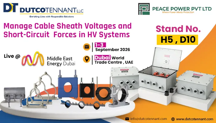
Middle East Energy Dubai 2026 is taking place from 1–3 September 2026 at Dubai World Trade Centre, bringing together industry professionals and technologies across the electrical and energy sectors. Dutco Tennant is also participating at Hall H5, Stand D10, where its electrical and energy portfolio will form part of the wider exchange around solutions for utilities, power networks, industrial facilities and infrastructure projects.
For professionals exploring high voltage link boxes, cable sheath bonding, HV cable cleats, trefoil cleats and other technologies related to cable-system reliability, the exhibition creates a relevant setting to connect technical requirements with available solutions.
Alongside other Electrical products at MEE Dubai, solutions that address cable grounding, mechanical restraint and fault protection remain important as power networks become more demanding.
A Coordinated Approach to HV Cable Protection
Reliable HV cable operation depends on managing different types of stress rather than relying on a single protective component.
Link boxes address the electrical side of cable sheath protection by providing controlled bonding and grounding connections. Cross-bonding configurations can help manage induced sheath voltages and losses, while a link box with SVL can provide additional protection against excessive transient sheath voltage where required.
Cable cleats address the mechanical side by securing cables in their intended position and restraining the forces generated during fault conditions. Whether the installation uses single cable cleats, trefoil cable cleats, aluminium cable cleats or another suitable configuration, selection needs to reflect the cable system and expected mechanical forces.
Peace Power's Link Boxes and Cable Cleats & Clamps address these complementary requirements across HV cable installations. By considering sheath bonding, grounding, fault current, cable formation, mechanical restraint and maintenance requirements together, project teams can develop a more coordinated approach to High Voltage Cable Protection and long-term system reliability.